Flyback Converter Diode
A flyback diode is a diode connected across an inductor used to eliminate flyback which is the sudden voltage spike seen across an inductive load when its supply current is suddenly reduced or interrupted. The flyback converter is a buck boost converter with the inductor split to form a transformer so that the voltage ratios are multiplied with an additional advantage of isolation.

Power Tips Design Considerations Of High Voltage Converters

Embedded Based Flyback Converter With Programmable Switching

Flyback Converter An Overview Sciencedirect Topics
For the flyback converter the input capacitor supplies the input current when the diode rectifier is off.

Flyback converter diode. It is used in circuits in which inductive loads are controlled by switches and in switching power supplies and inverters. When the switch turned off the polarity of primary and secondary coil voltages reversed. In the flyback converter the diode at the secondary side only has to block a high voltage while the current is low ipeakn.
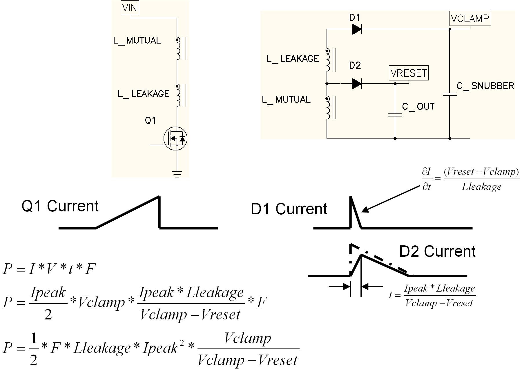
There will sharp voltage spike when power to inductive load ie. This makes it possible to select a diode with smaller capacitances and hence higher switching speed. Goerke abstract while using a snubber circuit is very common for flyback design suppressing the stress of mosfet is not the only design consideration for snubber.
When driving for example a plasma lamp or a voltage multiplier the rectifying diode of the boost converter is left out and the device is called a flyback transformer. Coils and other inductors are turned off. The advantage of a diode zener clamp is that the circuit.
During the switchsw is in on position the current builds up in the transformer primary and thus storing energy. Freewheel diode or flyback diodes are basically connected across inductive coils to prevent from voltage spikes in case of power getting turned off to the devices. So in our example for a 5v input the secondary winding will develop 15v across it during the charging of the primary.
Flyback transformer design considerations. With a flyback converter the anode of the secondary rectifier diode will see the same voltage but multiplied by the turns ratio. All this results in reduced losses and an increased efficiency.
Its derivation is illustrated in fig. Although it may be possible to design a flyback converter to work with dcm as well as ccm modes one thing must be remembered that during the transition from dcm to ccm mode this shifting function transforms into a 2 pole operation giving rise to low impedance for the converter. Choosing standard recovery diode or ultra fast diode in snubber kening gao ulrich b.
Voltage clamp snubber derivation of the flyback converter the flyback converter is based on the buck boost converter. Figure 1a depicts the basic buck boost converter with the switch realized using a mosfet and diode. The snubber circuit will also impact the efficiency standby power and emi performance.
The voltage discharge on the input capacitor due to the input average current should be within the. The simplified working principle of flyback converter is given below.

Lower Emi And Quiet Switching With The Fly Buck Topology

Is A Flyback Diode Needed If There Are Only Inductive

Freewheeling Diode Or Flyback Diode Circuit Working And Its

Edn Power Tips 17 Snubbing The Flyback Converter

Input Capacitor Rating Of Flyback Converter All About Circuits

Edn Fixing Emi Across The Board Part 5 In The Series

Solved Problem 7 A Flyback Converter Shown Below Is Op

Flyback Converter Design

Designing Isolated Flyback Converter Circuits Transformer

Switching Power Supply Topologies And Design Fundamentals

Flyback Converter Wikipedia
What Is The Difference Between A Flyback Converter And A
Comments
Post a Comment